How to Design an F341 HDMS Absalon Size 1:75 Frigate, with ASW Capability
This site documents how to build a scaled model of the F341. The model is designed for ASW, as I expect the ship to look after the update with TAS and ATAS in a few years.
Some of the drawings are done in scale 1:1 and afterwards scaled to 1:75, which I can manage in my 3D printer — equal to a total model length of around 2 metres (78 inches). Other parts are designed directly in 1:75 scale.
All the material used to design the model is public, and the internal parts are optimised for use with small servo motors. The internal "hidden" parts are not identical to the original ship.
I have emphasised that all essential parts can be controlled (moved) via an RC remote control system (guns, radar, TAS system, gates, RIB, rudder, bow propeller, etc.).
During 2022, the frigate F341 has undergone a significant update — stability has been improved and close-in defence capability has been enhanced with the installation of a Laser CIWS (see Main Overhaul 2022).
Information and Links to the Real World
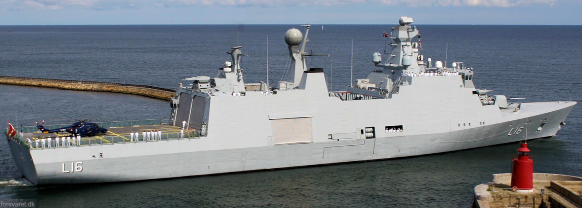
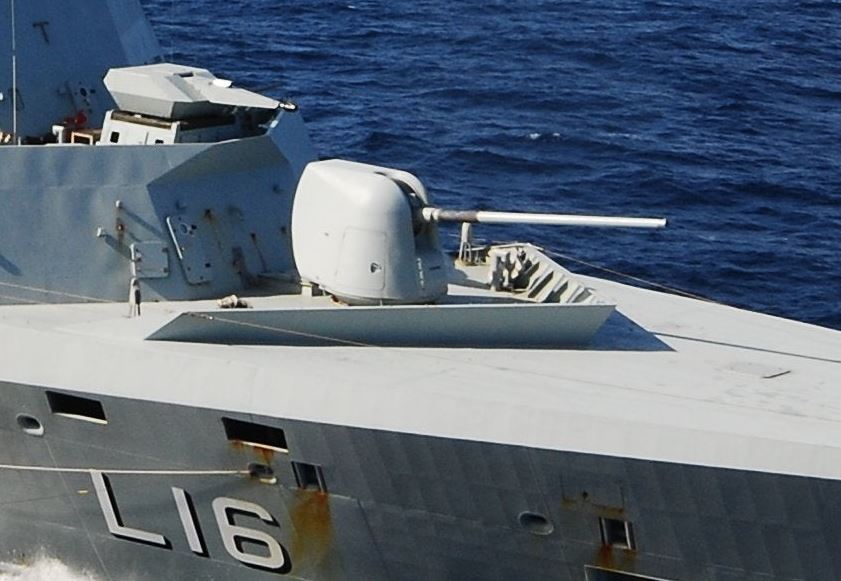
The real HDMS Absalon (F341)
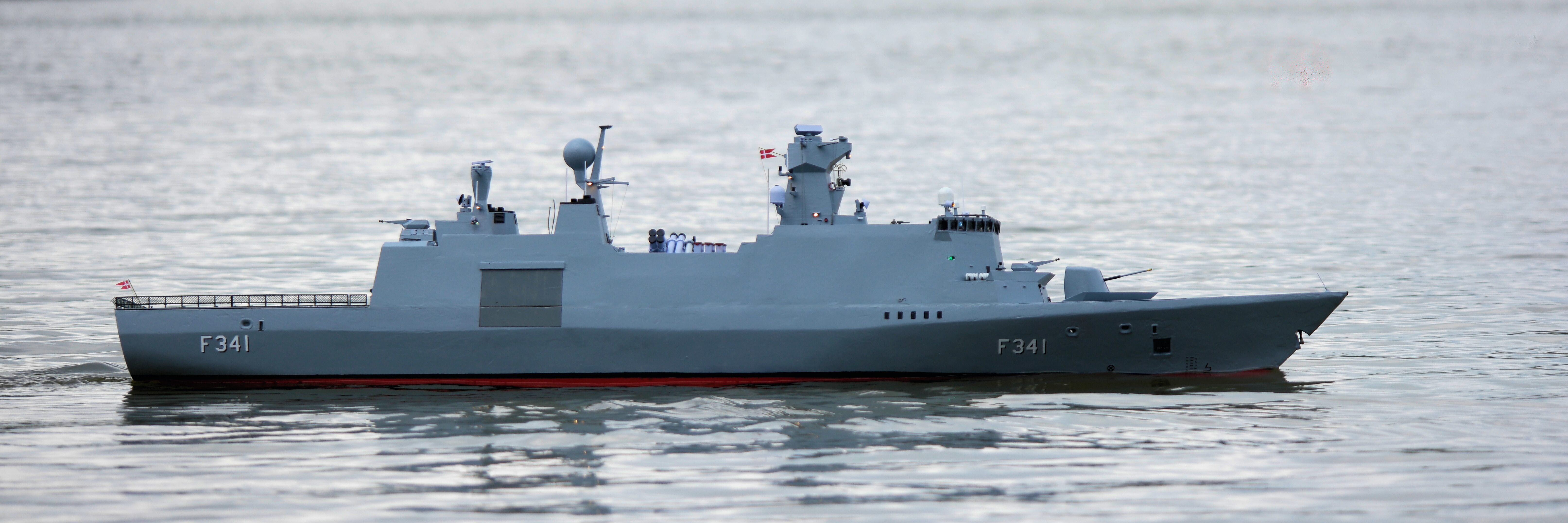
The 1:75 scale model. I can receive telemetry data from the ship — power consumption on main engines and battery data. Video from the ship is available via a separate 5.8 GHz link.
Bridge Close-ups & First Sailing
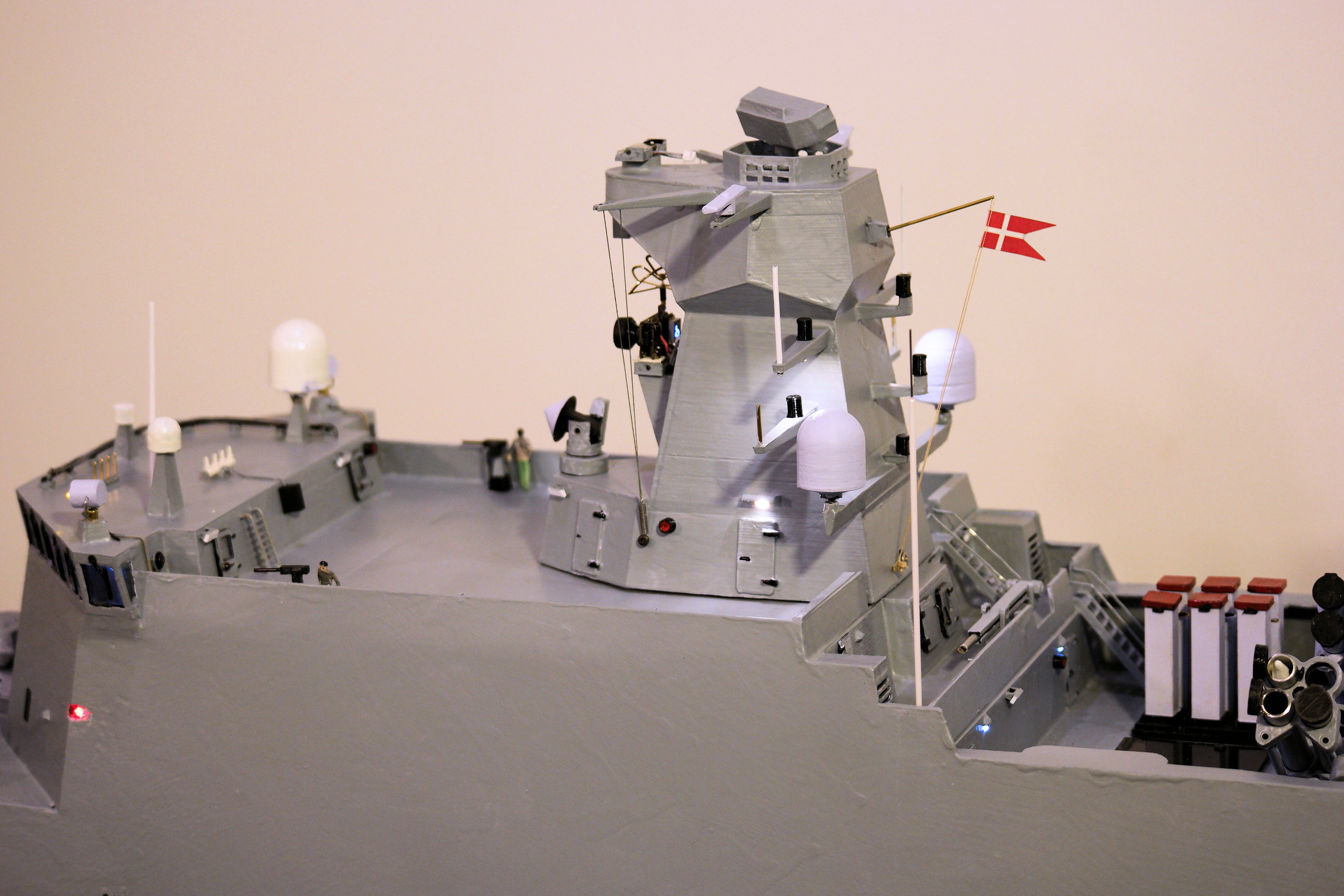
Close-ups of the bridge
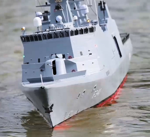
Pictures from the first test sailing in a lake (click for video)
Hull Construction
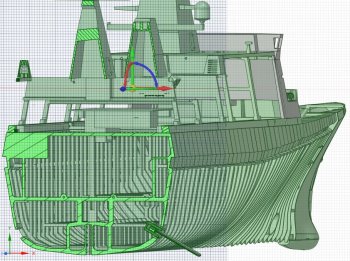
The first thing I drew was all frames — the outer contour is given, but the inside must be adapted to all the parts that will later be built into the ship.
It is very difficult to wait to 3D print the parts that you have already drawn, but everything has to be thought through, otherwise there is a good chance that you will have to draw it all over again.
I use "PETG" as the standard 3D material because it is very strong and fairly easy to use. The disadvantage is that it is very difficult to glue, so I usually use a solvent (Methylene chloride, CH₂Cl₂) — with the necessary respiratory protection.
The upper part of the ship is coated with 1.5 mm ABS. ABS is wonderfully easy to use because you can "melt" ABS together with PETG by using a suitable solvent.
Hull construction (click for video)
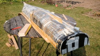
Continuation of hull construction (click for video)
Rudder Design
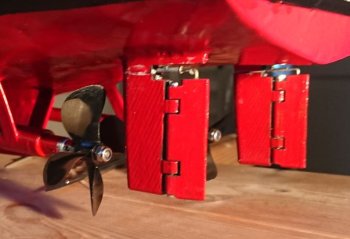
The rudder was a lot of fun to draw — it is double acting where the outer part rotates much more than the inner part. The centre of the two axes is offset from each other. It required 6 iterations before it worked satisfactorily.
Then I started drawing each frame, with room for sonar, main motors, gearbox, batteries, servos, etc.
Rudder animation (click for video)
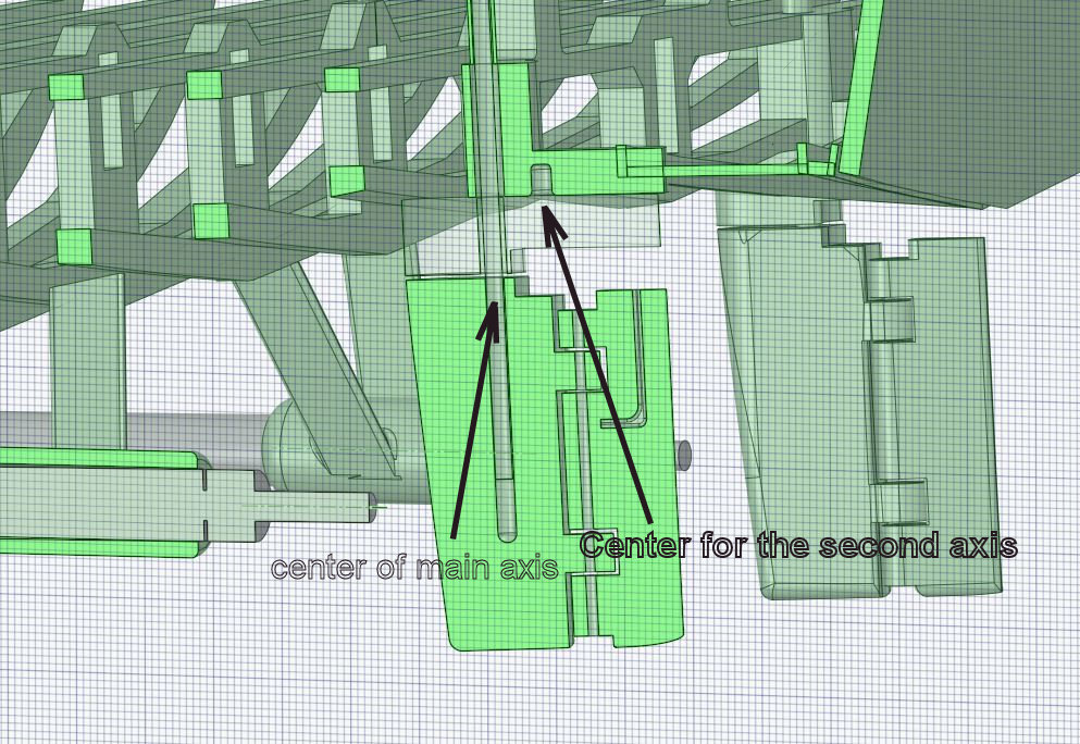
Rudder 3D drawing
Cannon Design
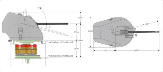
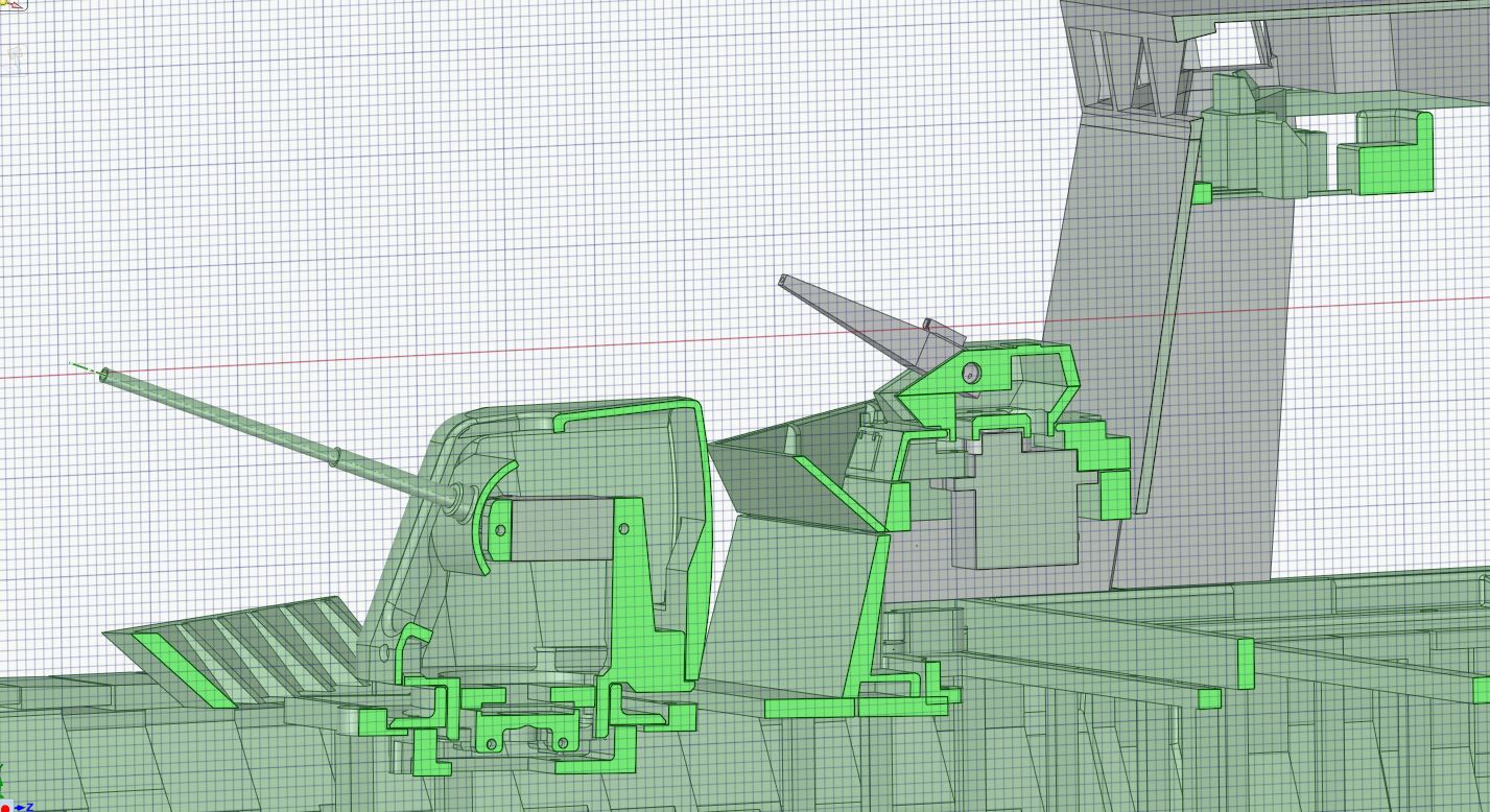
The main cannon is a 5" (127 mm), and the F341 also has two 35 mm CIWS (Close-In Weapon System). Starting point is 2D drawings from the manufacturer BAE Systems, then I replaced the inside to fit two small servo motors for horizontal and vertical rotation. In the small 35 mm cannon there is only room for one horizontal servo.
127 mm main cannon — 3D design
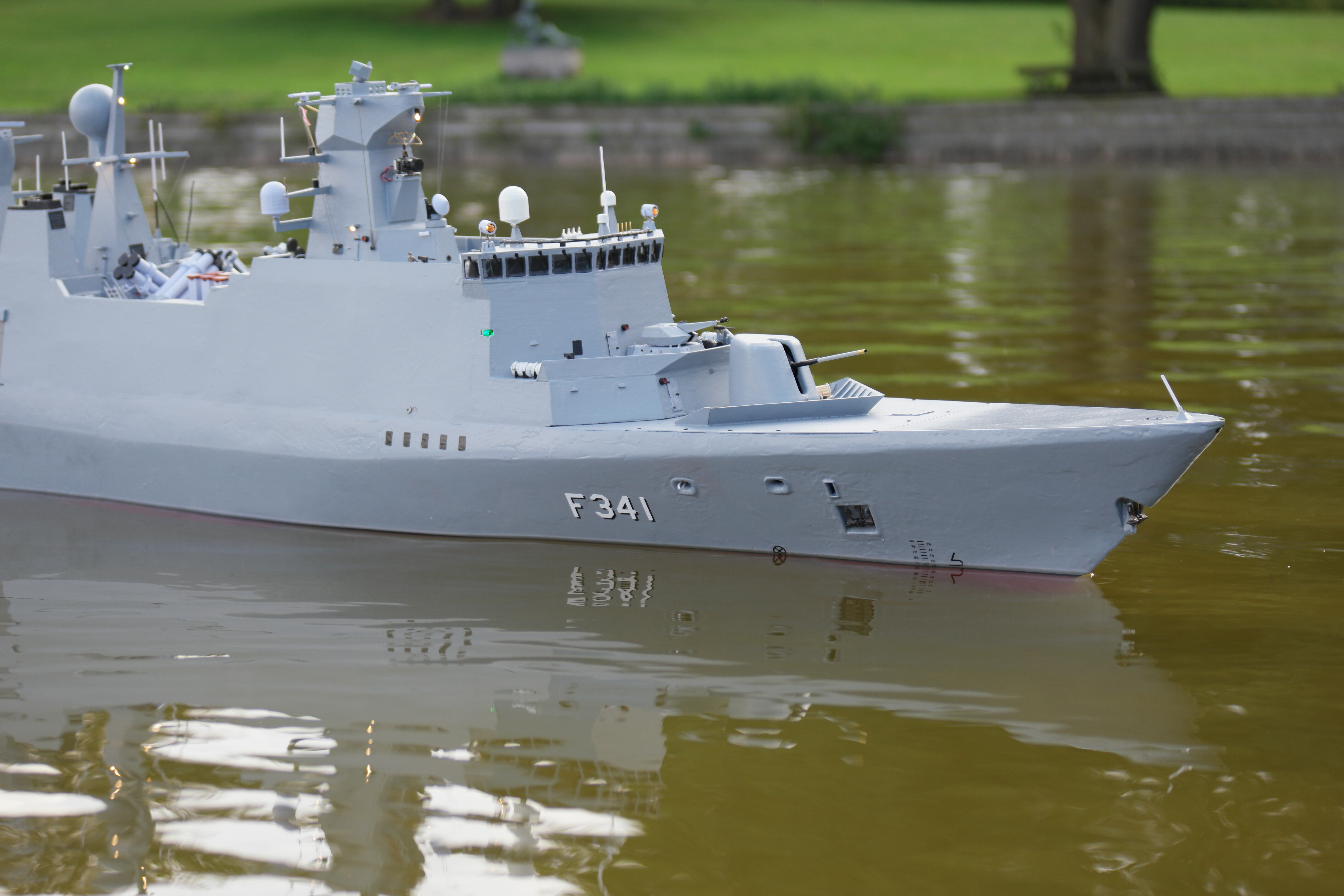
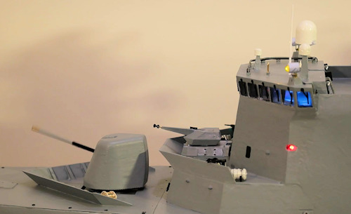
127 mm mounted on the model
35 mm CIWS reference
35 mm CIWS — 3D design
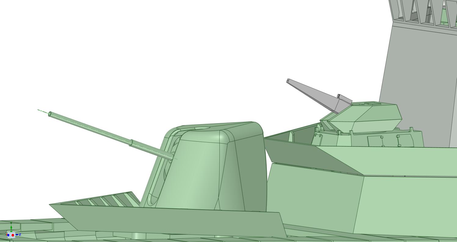
35 mm CIWS — detail view
Videos & CIWS in Action
127 mm cannon in action (click for video)
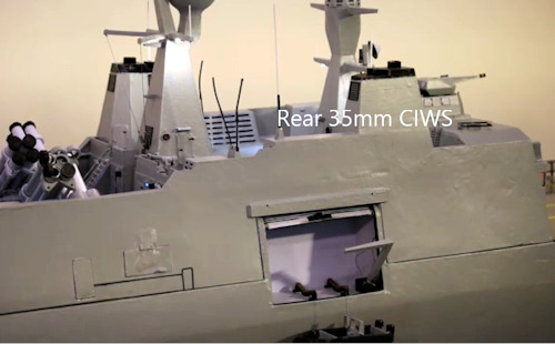
Rear CIWS in action (click for video)
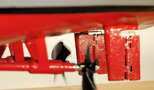
Drive shafts and rudder in action — on the rudder you can see that the parts are 3D printed, even though the resolution is better than 0.15 mm (click for video)
F341 Specification
Download the F341 Specification (PDF) — a comparison between the real ship and the model.